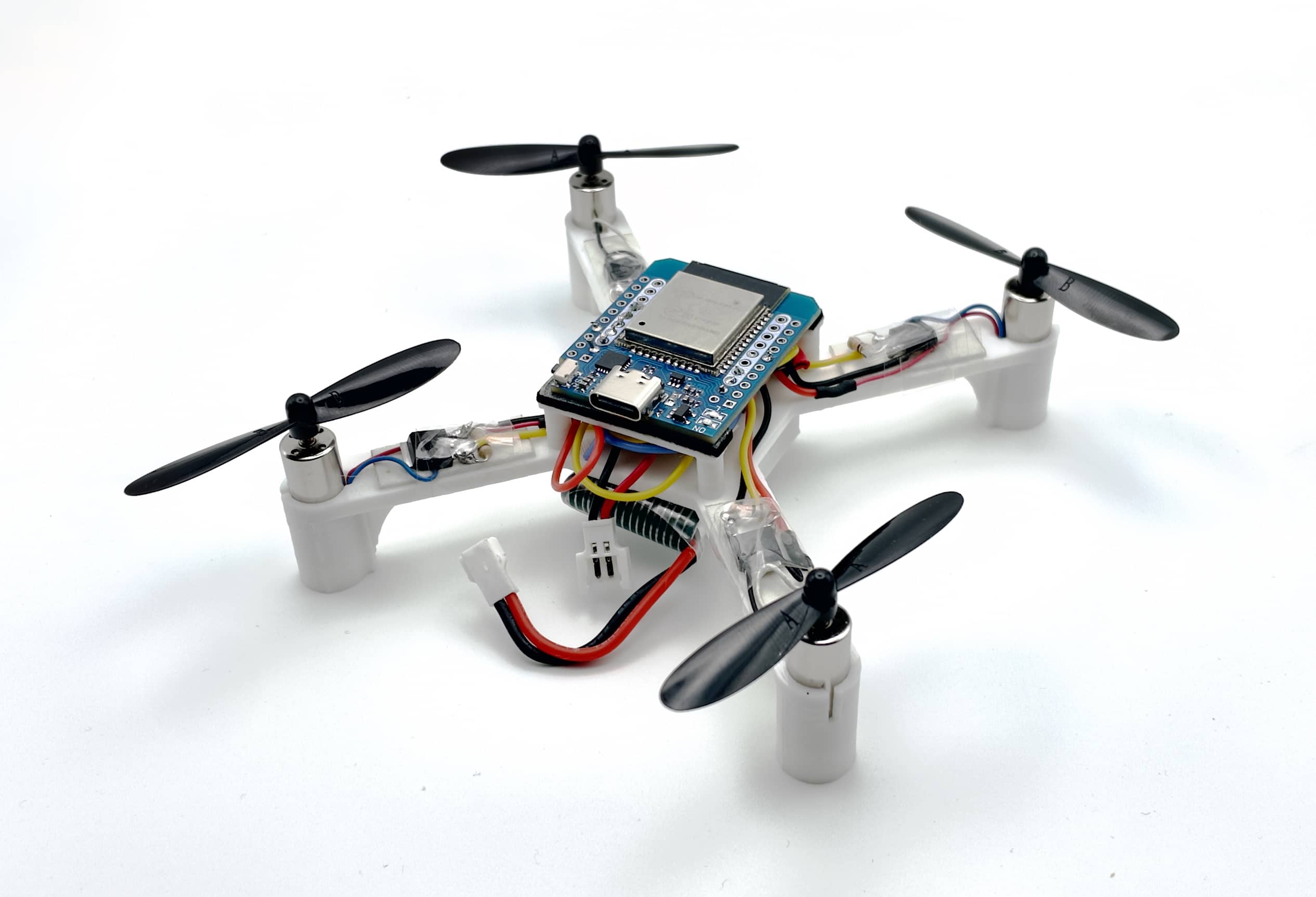
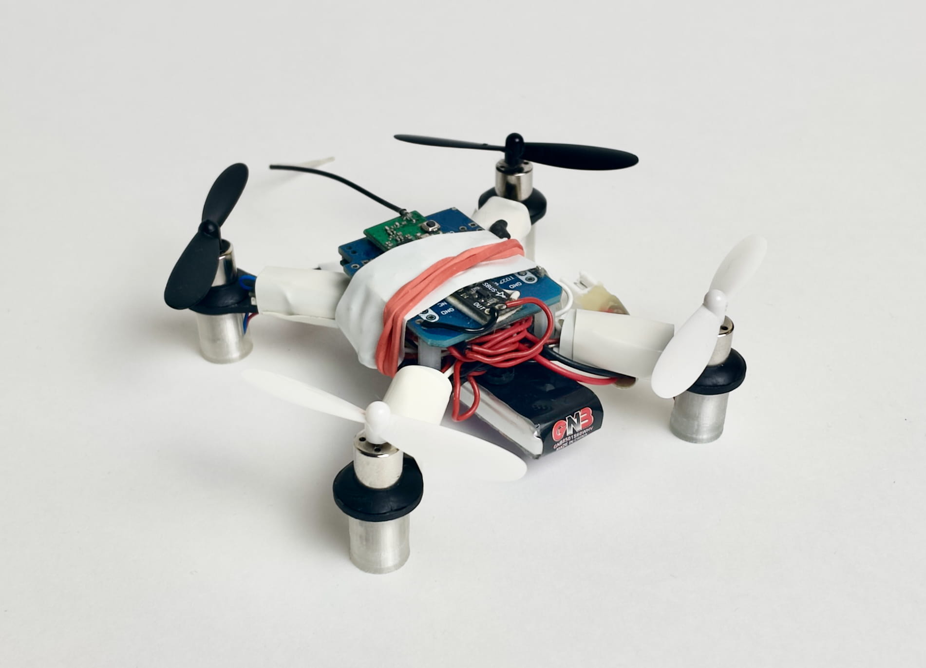
| Version 1.1 (3D-printed frame) | Version 0 |
|
|
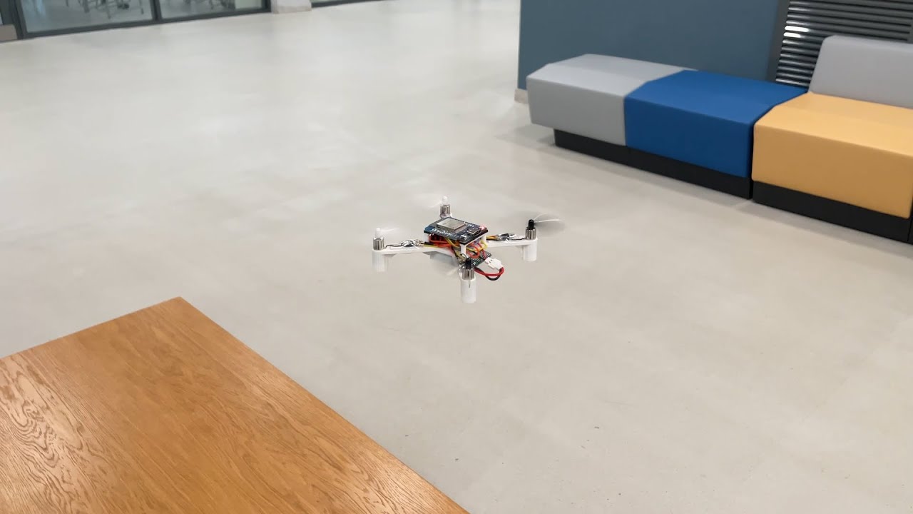 Version 0 demo video: https://youtu.be/8GzzIQ3C6DQ.
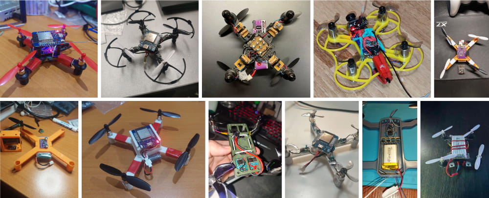
 See the [user builds gallery](docs/user.md).
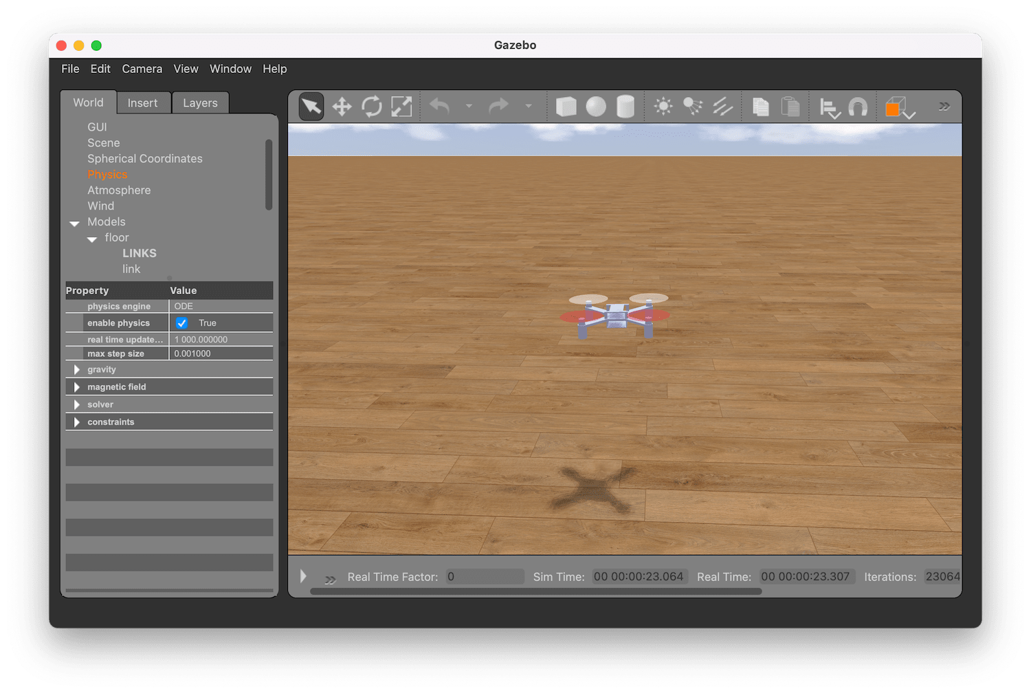
 ## Simulation
The simulator is implemented using Gazebo and runs the original Arduino code:
## Simulation
The simulator is implemented using Gazebo and runs the original Arduino code:
 ## Articles
* [Assembly instructions](docs/assembly.md).
* [Building and running the code](docs/build.md).
* [Troubleshooting](docs/troubleshooting.md).
* [Firmware architecture overview](docs/firmware.md).
* [Log analysis](docs/log.md).
* [User builds gallery](docs/user.md).
## Components
|Type|Part|Image|Quantity|
|-|-|:-:|:-:|
|Microcontroller board|ESP32 Mini|
## Articles
* [Assembly instructions](docs/assembly.md).
* [Building and running the code](docs/build.md).
* [Troubleshooting](docs/troubleshooting.md).
* [Firmware architecture overview](docs/firmware.md).
* [Log analysis](docs/log.md).
* [User builds gallery](docs/user.md).
## Components
|Type|Part|Image|Quantity|
|-|-|:-:|:-:|
|Microcontroller board|ESP32 Mini|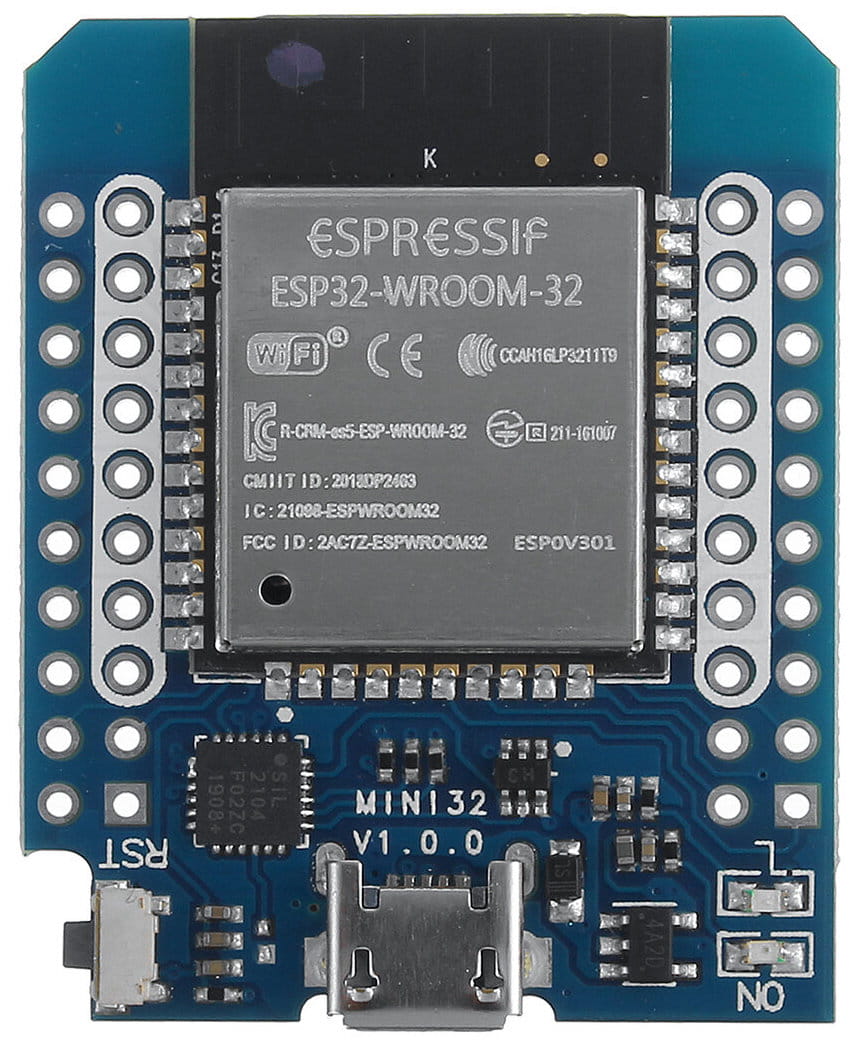 |1|
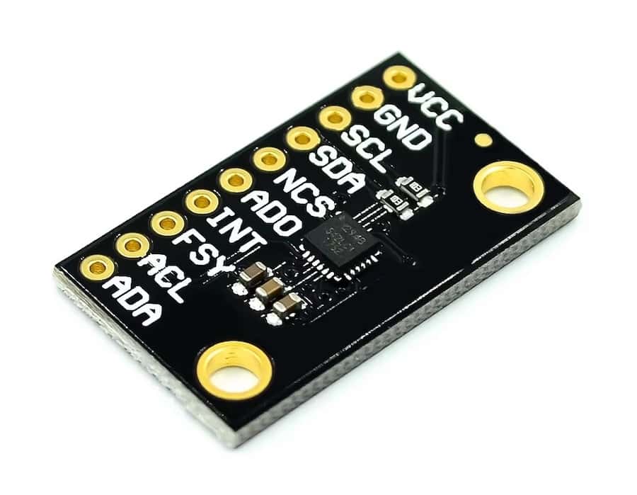
|IMU (and barometer²) board|GY‑91, MPU-9265 (or other MPU‑9250/MPU‑6500 board), ICM‑20948³|
|1|
|IMU (and barometer²) board|GY‑91, MPU-9265 (or other MPU‑9250/MPU‑6500 board), ICM‑20948³|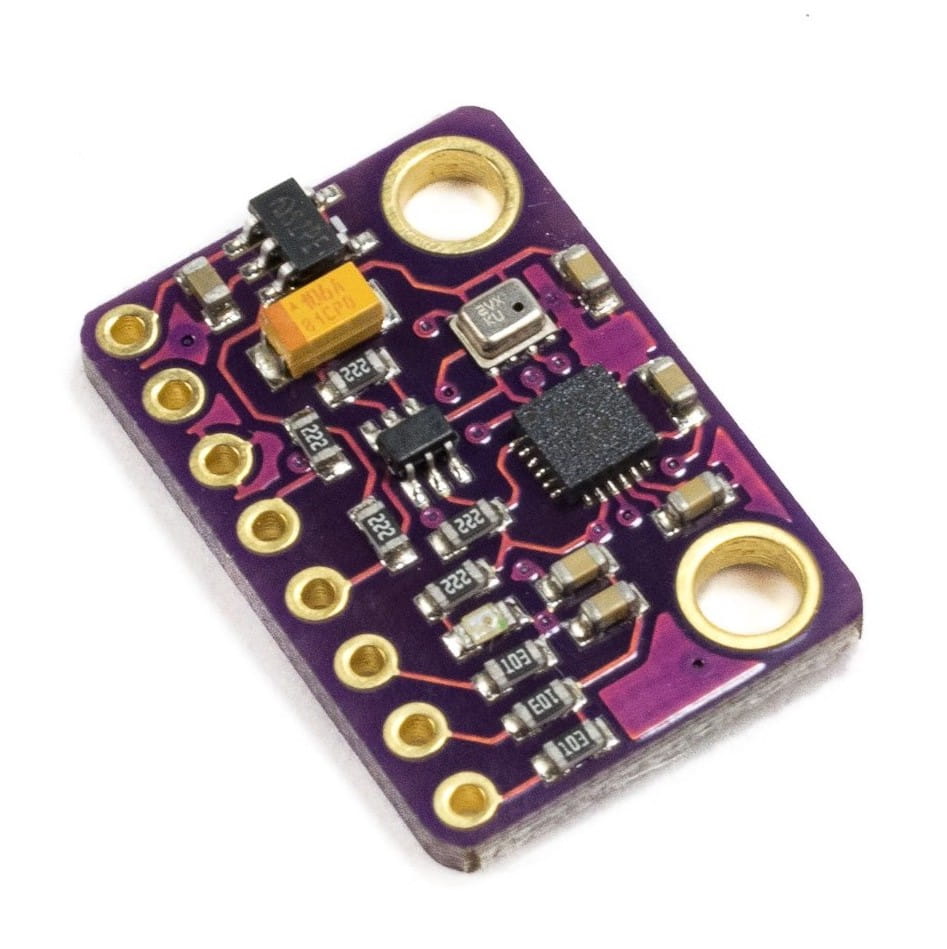
 |1|
|(Recommended) Buck-boost converter|To be determined, output 5V or 3.3V, see [user-contributed schematics](https://miro.com/app/board/uXjVN-dTjoo=/?moveToWidget=3458764612179508274&cot=14)|
|1|
|(Recommended) Buck-boost converter|To be determined, output 5V or 3.3V, see [user-contributed schematics](https://miro.com/app/board/uXjVN-dTjoo=/?moveToWidget=3458764612179508274&cot=14)|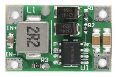 |1|
|Motor|8520 3.7V brushed motor (shaft 0.8mm).
|1|
|Motor|8520 3.7V brushed motor (shaft 0.8mm).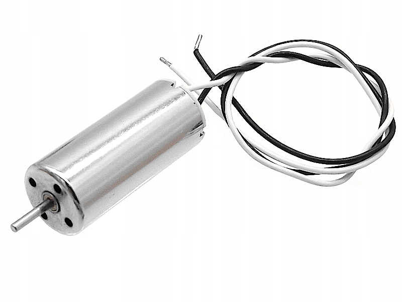 |4|
|Propeller|Hubsan 55 mm|
|4|
|Propeller|Hubsan 55 mm|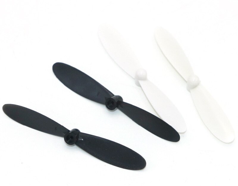 |4|
|MOSFET (transistor)|100N03A or [analog](https://t.me/opensourcequadcopter/33)|
|4|
|MOSFET (transistor)|100N03A or [analog](https://t.me/opensourcequadcopter/33)|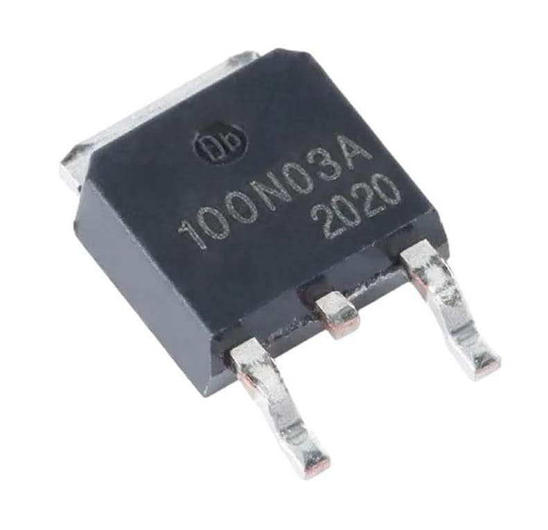 |4|
|Pull-down resistor|10 kΩ|
|4|
|Pull-down resistor|10 kΩ|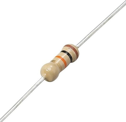 |4|
|3.7V Li-Po battery|LW 952540 (or any compatible by the size)|
|4|
|3.7V Li-Po battery|LW 952540 (or any compatible by the size)| |1|
|Battery connector cable|MX2.0 2P female|
|1|
|Battery connector cable|MX2.0 2P female| |1|
|Li-Po Battery charger|Any|
|1|
|Li-Po Battery charger|Any| |1|
|Screws for IMU board mounting|M3x5|
|1|
|Screws for IMU board mounting|M3x5|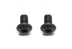 |2|
|Screws for frame assembly|M1.4x5|
|2|
|Screws for frame assembly|M1.4x5|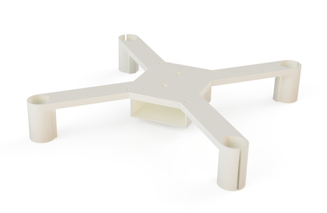 |1|
|Frame top part|3D printed:
|1|
|Frame top part|3D printed: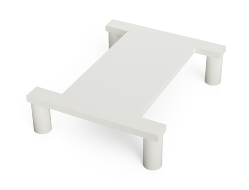 |1|
|Washer for IMU board mounting|3D printed:
|1|
|Washer for IMU board mounting|3D printed: |2|
|*RC transmitter (optional)*|*KINGKONG TINY X8 (warning: lacks USB support) or other⁵*|
|2|
|*RC transmitter (optional)*|*KINGKONG TINY X8 (warning: lacks USB support) or other⁵*|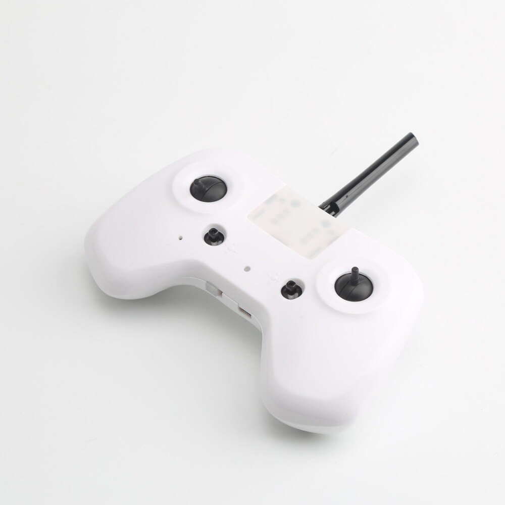 |1|
|*RC receiver (optional)*|*DF500 or other⁵*|
|1|
|*RC receiver (optional)*|*DF500 or other⁵*|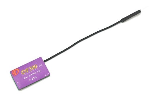 |1|
|Wires|28 AWG recommended|
|1|
|Wires|28 AWG recommended| ||
|Tape, double-sided tape||||
*² — barometer is not used for now.*
||
|Tape, double-sided tape||||
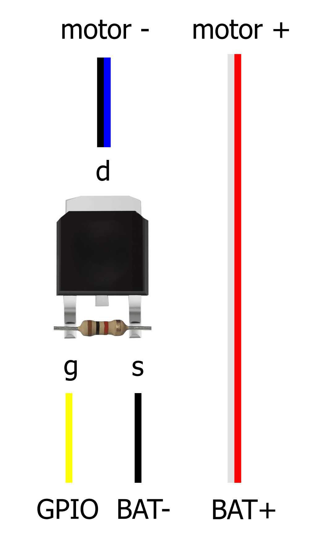
*² — barometer is not used for now.* Motor connection scheme:
 You can see a user-contributed [variant of complete circuit diagram](https://miro.com/app/board/uXjVN-dTjoo=/?moveToWidget=3458764612338222067&cot=14) of the drone.
See [assembly guide](docs/assembly.md) for instructions on assembling the drone.
### Notes
* Power ESP32 Mini with Li-Po battery using VCC (+) and GND (-) pins.
* Connect the IMU board to the ESP32 Mini using VSPI, power it using 3.3V and GND pins:
|IMU pin|ESP32 pin|
|-|-|
|GND|GND|
|3.3V|3.3V|
|SCL *(SCK)*|SVP (GPIO18)|
|SDA *(MOSI)*|GPIO23|
|SAO *(MISO)*|GPIO19|
|NCS|GPIO5|
* Solder pull-down resistors to the MOSFETs.
* Connect the motors to the ESP32 Mini using MOSFETs, by following scheme:
|Motor|Position|Direction|Wires|GPIO|
|-|-|-|-|-|
|Motor 0|Rear left|Counter-clockwise|Black & White|GPIO12 (*TDI*)|
|Motor 1|Rear right|Clockwise|Blue & Red|GPIO13 (*TCK*)|
|Motor 2|Front right|Counter-clockwise|Black & White|GPIO14 (*TMS*)|
|Motor 3|Front left|Clockwise|Blue & Red|GPIO15 (*TD0*)|
Counter-clockwise motors have black and white wires and clockwise motors have blue and red wires.
* Optionally connect the RC receiver to the ESP32's UART2:
|Receiver pin|ESP32 pin|
|-|-|
|GND|GND|
|VIN|VCC (or 3.3V depending on the receiver)|
|Signal (TX)|GPIO4⁶|
*⁶ — UART2 RX pin was [changed](https://docs.espressif.com/projects/arduino-esp32/en/latest/migration_guides/2.x_to_3.0.html#id14) to GPIO4 in Arduino ESP32 core 3.0.*
### IMU placement
Default IMU orientation in the code is **LFD** (Left-Forward-Down):
You can see a user-contributed [variant of complete circuit diagram](https://miro.com/app/board/uXjVN-dTjoo=/?moveToWidget=3458764612338222067&cot=14) of the drone.
See [assembly guide](docs/assembly.md) for instructions on assembling the drone.
### Notes
* Power ESP32 Mini with Li-Po battery using VCC (+) and GND (-) pins.
* Connect the IMU board to the ESP32 Mini using VSPI, power it using 3.3V and GND pins:
|IMU pin|ESP32 pin|
|-|-|
|GND|GND|
|3.3V|3.3V|
|SCL *(SCK)*|SVP (GPIO18)|
|SDA *(MOSI)*|GPIO23|
|SAO *(MISO)*|GPIO19|
|NCS|GPIO5|
* Solder pull-down resistors to the MOSFETs.
* Connect the motors to the ESP32 Mini using MOSFETs, by following scheme:
|Motor|Position|Direction|Wires|GPIO|
|-|-|-|-|-|
|Motor 0|Rear left|Counter-clockwise|Black & White|GPIO12 (*TDI*)|
|Motor 1|Rear right|Clockwise|Blue & Red|GPIO13 (*TCK*)|
|Motor 2|Front right|Counter-clockwise|Black & White|GPIO14 (*TMS*)|
|Motor 3|Front left|Clockwise|Blue & Red|GPIO15 (*TD0*)|
Counter-clockwise motors have black and white wires and clockwise motors have blue and red wires.
* Optionally connect the RC receiver to the ESP32's UART2:
|Receiver pin|ESP32 pin|
|-|-|
|GND|GND|
|VIN|VCC (or 3.3V depending on the receiver)|
|Signal (TX)|GPIO4⁶|
*⁶ — UART2 RX pin was [changed](https://docs.espressif.com/projects/arduino-esp32/en/latest/migration_guides/2.x_to_3.0.html#id14) to GPIO4 in Arduino ESP32 core 3.0.*
### IMU placement
Default IMU orientation in the code is **LFD** (Left-Forward-Down):
 In case of using other IMU orientation, modify the `rotateIMU` function in the `imu.ino` file.
See [FlixPeriph documentation](https://github.com/okalachev/flixperiph?tab=readme-ov-file#imu-axes-orientation) to learn axis orientation of other IMU boards.
## Version 0
See the information on the obsolete version 0 in the [corresponding article](docs/version0.md).
## Materials
Subscribe to the Telegram channel on developing the drone and the flight controller (in Russian): https://t.me/opensourcequadcopter.
Join the official Telegram chat: https://t.me/opensourcequadcopterchat.
Detailed article on Habr.com about the development of the drone (in Russian): https://habr.com/ru/articles/814127/.
In case of using other IMU orientation, modify the `rotateIMU` function in the `imu.ino` file.
See [FlixPeriph documentation](https://github.com/okalachev/flixperiph?tab=readme-ov-file#imu-axes-orientation) to learn axis orientation of other IMU boards.
## Version 0
See the information on the obsolete version 0 in the [corresponding article](docs/version0.md).
## Materials
Subscribe to the Telegram channel on developing the drone and the flight controller (in Russian): https://t.me/opensourcequadcopter.
Join the official Telegram chat: https://t.me/opensourcequadcopterchat.
Detailed article on Habr.com about the development of the drone (in Russian): https://habr.com/ru/articles/814127/.