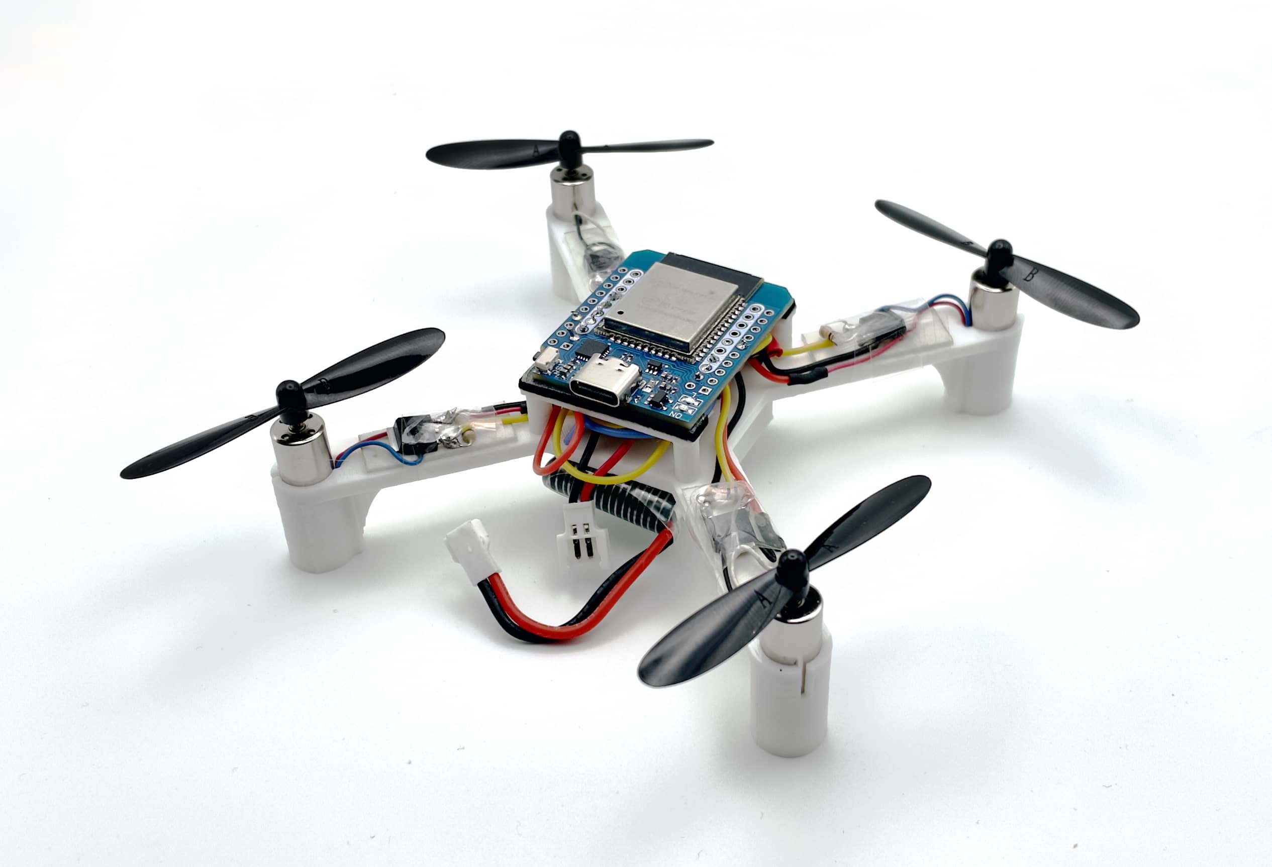
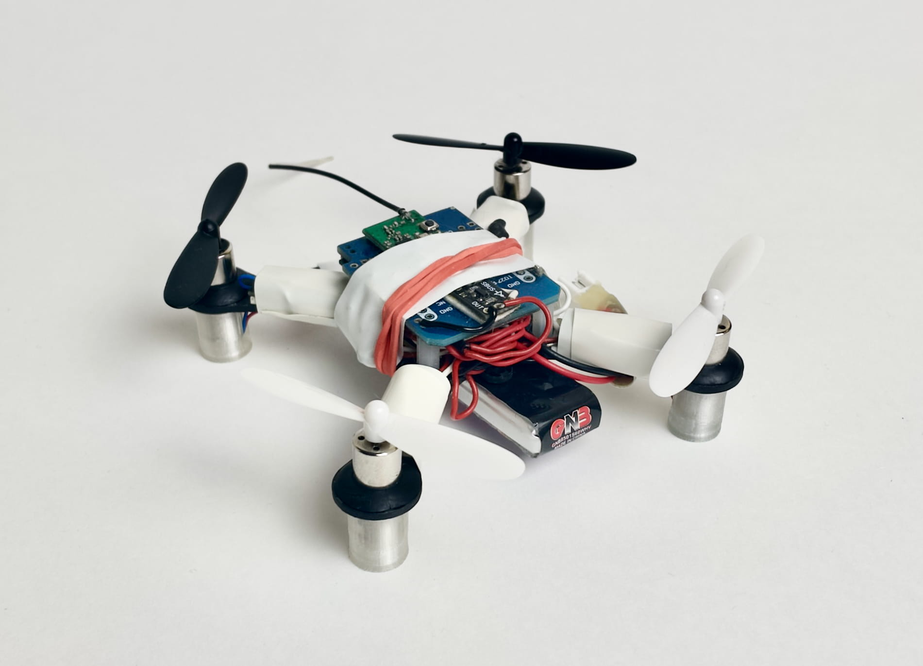
| Version 1.1 (3D-printed frame) | Version 0 |
|
|
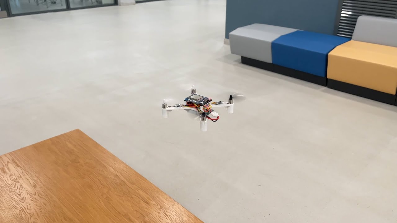 Version 0 demo video: https://youtu.be/8GzzIQ3C6DQ.
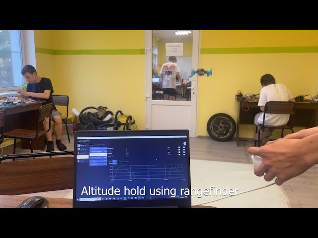
 Usage in education (RoboCamp): https://youtu.be/Wd3yaorjTx0.
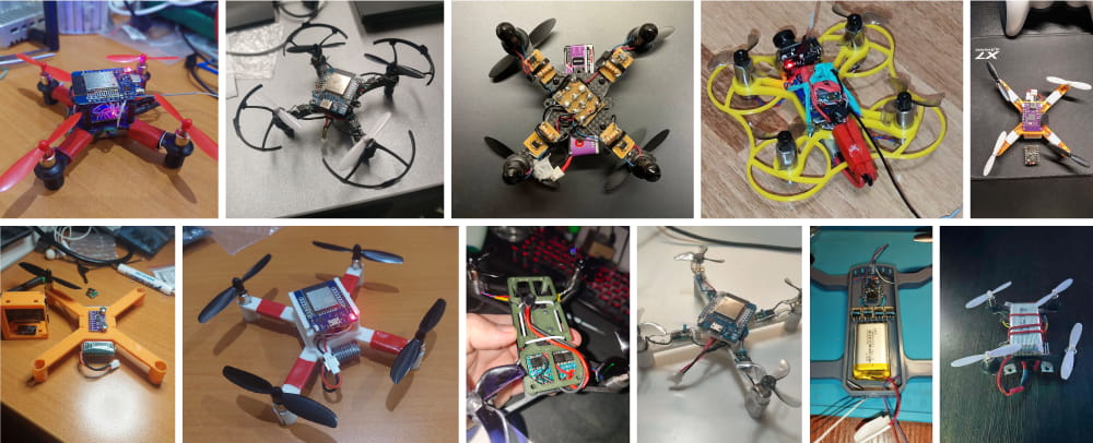
 See the [user builds gallery](docs/user.md):
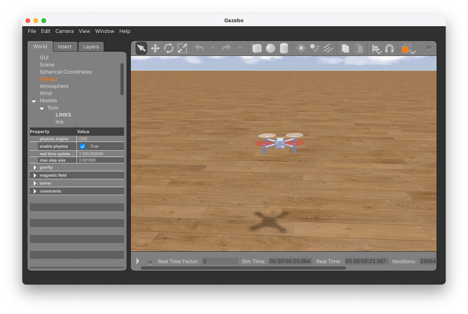
 ## Simulation
The simulator is implemented using Gazebo and runs the original Arduino code:
## Simulation
The simulator is implemented using Gazebo and runs the original Arduino code:
 ## Articles
* [Assembly instructions](docs/assembly.md).
* [Usage: build, setup and flight](docs/usage.md).
* [Troubleshooting](docs/troubleshooting.md).
* [Firmware architecture overview](docs/firmware.md).
* [Python library tutorial](tools/pyflix/README.md).
* [Log analysis](docs/log.md).
* [User builds gallery](docs/user.md).
## Components
|Type|Part|Image|Quantity|
|-|-|:-:|:-:|
|Microcontroller board|ESP32 Mini|
## Articles
* [Assembly instructions](docs/assembly.md).
* [Usage: build, setup and flight](docs/usage.md).
* [Troubleshooting](docs/troubleshooting.md).
* [Firmware architecture overview](docs/firmware.md).
* [Python library tutorial](tools/pyflix/README.md).
* [Log analysis](docs/log.md).
* [User builds gallery](docs/user.md).
## Components
|Type|Part|Image|Quantity|
|-|-|:-:|:-:|
|Microcontroller board|ESP32 Mini|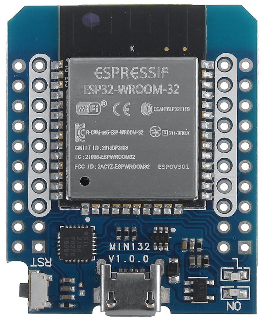 |1|
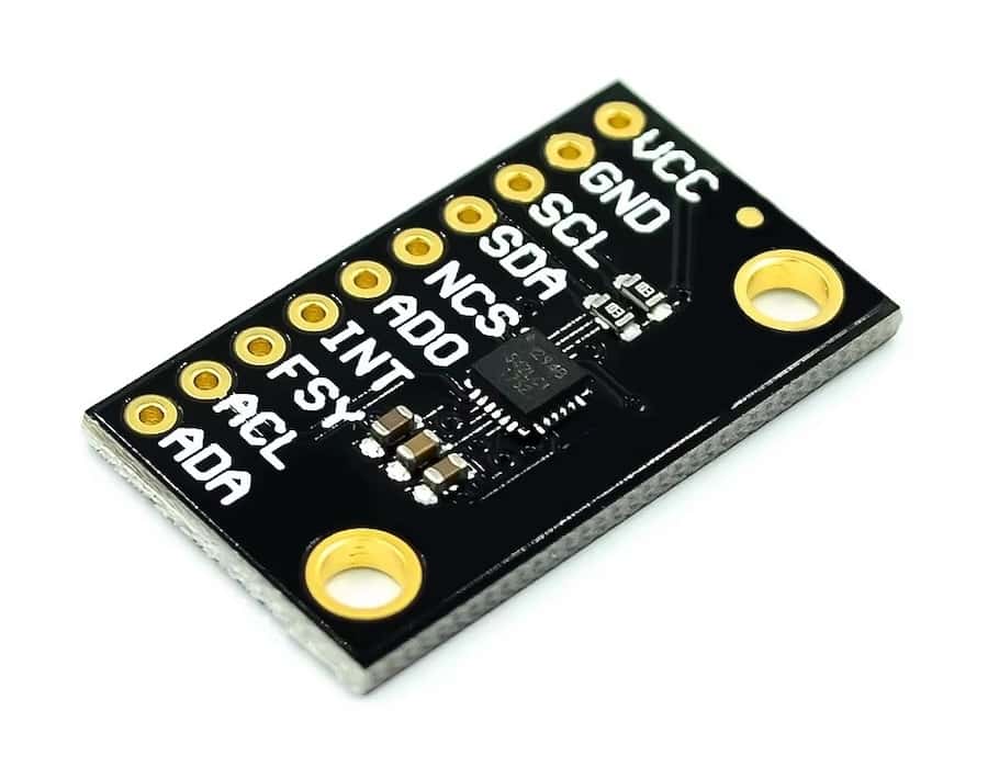
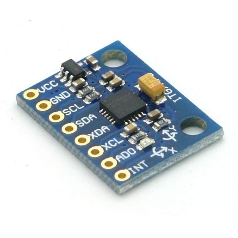
|IMU (and barometer²) board|GY‑91, MPU-9265 (or other MPU‑9250/MPU‑6500 board)
|1|
|IMU (and barometer²) board|GY‑91, MPU-9265 (or other MPU‑9250/MPU‑6500 board)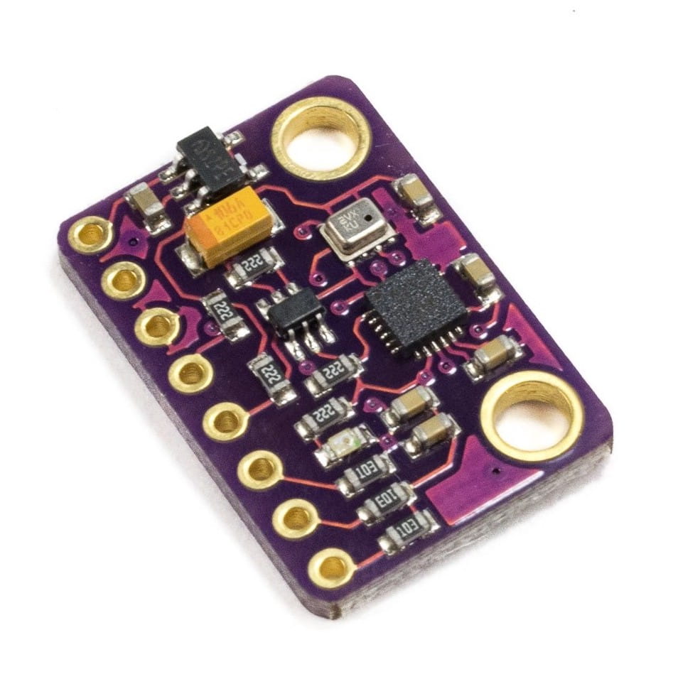
 |1|
|Buck-boost converter (recommended)|To be determined, output 5V or 3.3V, see [user-contributed schematics](https://miro.com/app/board/uXjVN-dTjoo=/?moveToWidget=3458764612179508274&cot=14)|
|1|
|Buck-boost converter (recommended)|To be determined, output 5V or 3.3V, see [user-contributed schematics](https://miro.com/app/board/uXjVN-dTjoo=/?moveToWidget=3458764612179508274&cot=14)|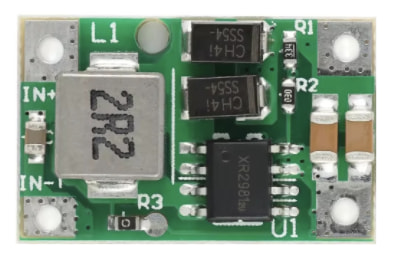 |1|
|Motor|8520 3.7V brushed motor (shaft 0.8mm).
|1|
|Motor|8520 3.7V brushed motor (shaft 0.8mm).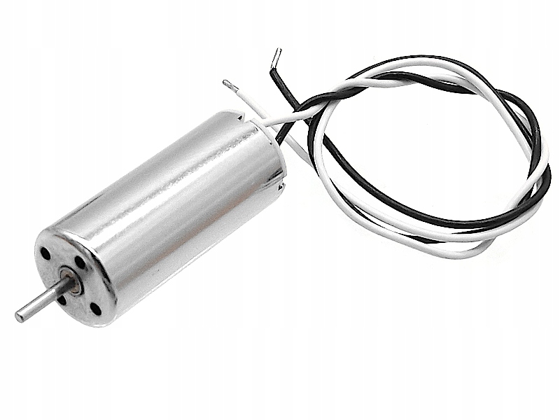 |4|
|Propeller|Hubsan 55 mm|
|4|
|Propeller|Hubsan 55 mm|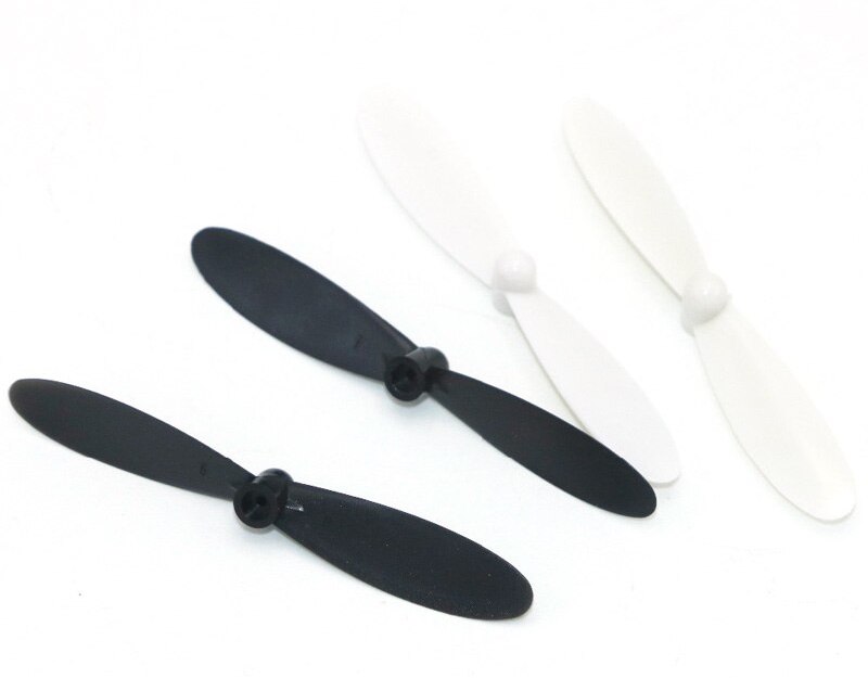 |4|
|MOSFET (transistor)|100N03A or [analog](https://t.me/opensourcequadcopter/33)|
|4|
|MOSFET (transistor)|100N03A or [analog](https://t.me/opensourcequadcopter/33)|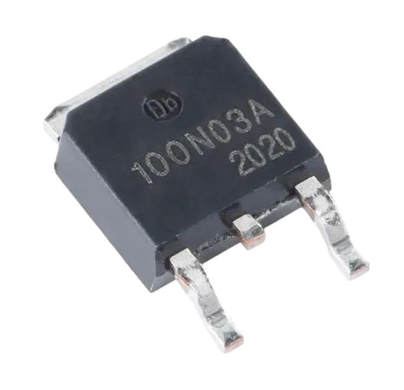 |4|
|Pull-down resistor|10 kΩ|
|4|
|Pull-down resistor|10 kΩ|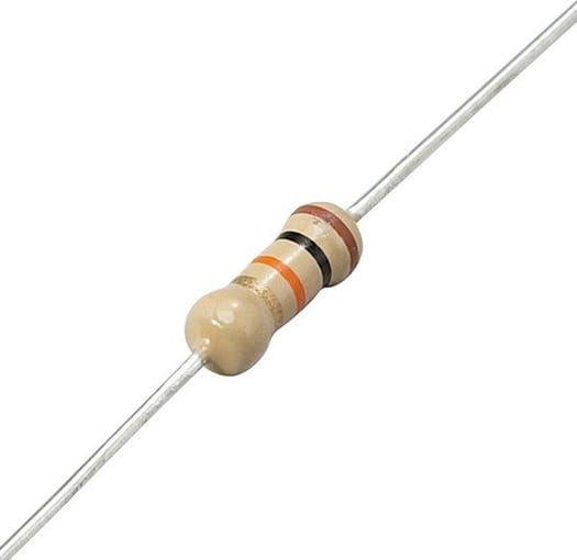 |4|
|3.7V Li-Po battery|LW 952540 (or any compatible by the size)|
|4|
|3.7V Li-Po battery|LW 952540 (or any compatible by the size)|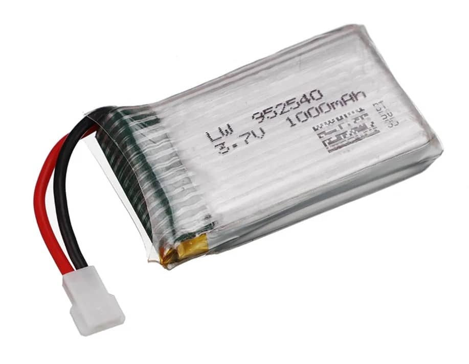 |1|
|Battery connector cable|MX2.0 2P female|
|1|
|Battery connector cable|MX2.0 2P female|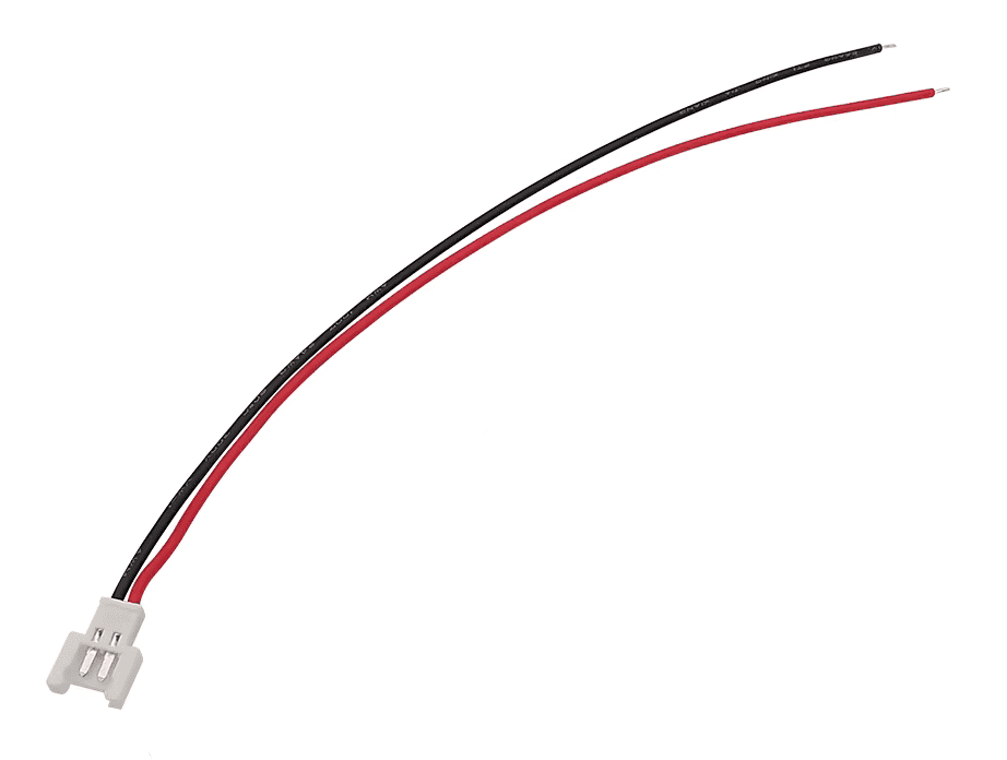 |1|
|Li-Po Battery charger|Any|
|1|
|Li-Po Battery charger|Any|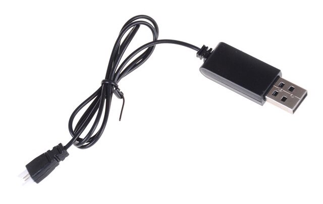 |1|
|Screws for IMU board mounting|M3x5|
|1|
|Screws for IMU board mounting|M3x5|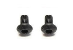 |2|
|Screws for frame assembly|M1.4x5|
|2|
|Screws for frame assembly|M1.4x5|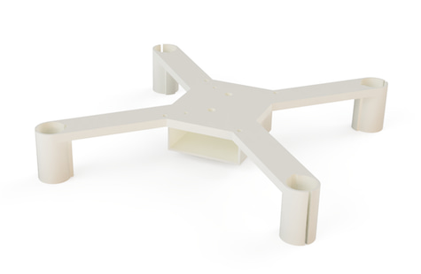 |1|
|Frame top part|3D printed:
|1|
|Frame top part|3D printed: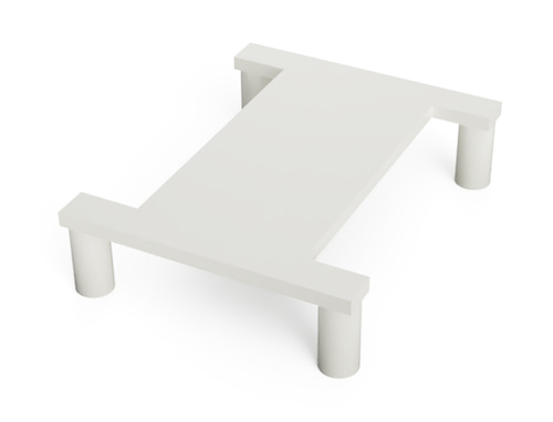 |1|
|Washer for IMU board mounting|3D printed:
|1|
|Washer for IMU board mounting|3D printed: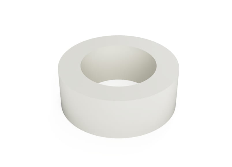 |2|
|Controller (recommended)|CC2500 transmitter, like BetaFPV LiteRadio CC2500 (RC receiver/Wi-Fi).
|2|
|Controller (recommended)|CC2500 transmitter, like BetaFPV LiteRadio CC2500 (RC receiver/Wi-Fi).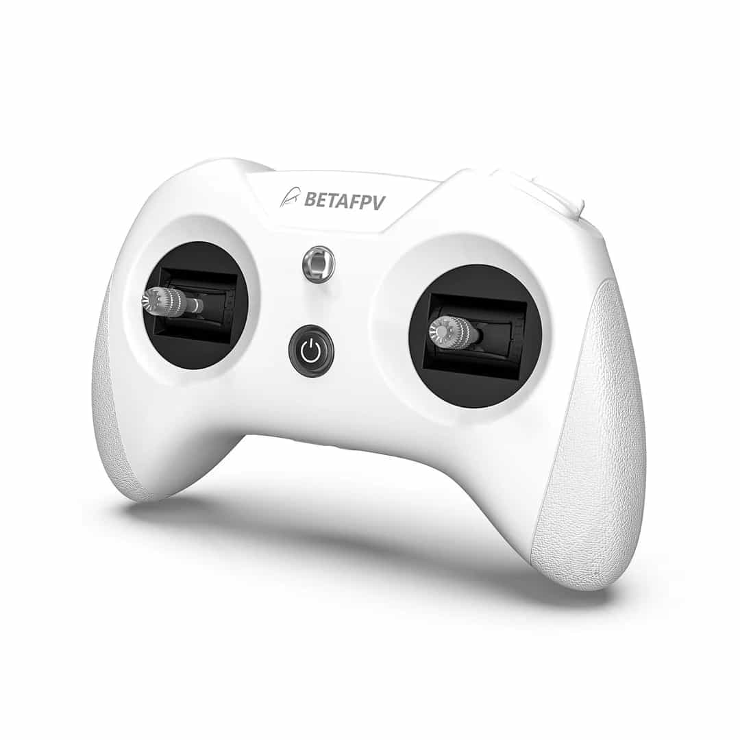
 |1|
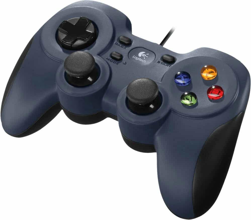
|*RC receiver (optional)*|*DF500 or other⁵*|
|1|
|*RC receiver (optional)*|*DF500 or other⁵*|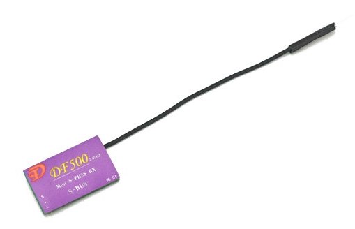 |1|
|Wires|28 AWG recommended|
|1|
|Wires|28 AWG recommended|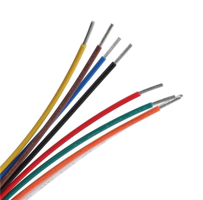 ||
|Tape, double-sided tape||||
*² — barometer is not used for now.*
||
|Tape, double-sided tape||||
*² — barometer is not used for now.* *(Dashed is optional).*
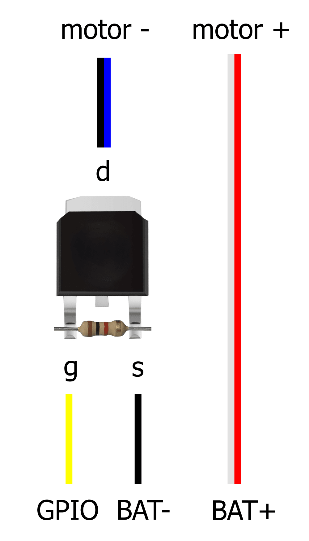
Motor connection scheme:
*(Dashed is optional).*
Motor connection scheme:
 You can see a user-contributed [variant of complete circuit diagram](https://miro.com/app/board/uXjVN-dTjoo=/?moveToWidget=3458764612338222067&cot=14) of the drone.
See [assembly guide](docs/assembly.md) for instructions on assembling the drone.
### Notes
* Power ESP32 Mini with Li-Po battery using VCC (+) and GND (-) pins.
* Connect the IMU board to the ESP32 Mini using VSPI, power it using 3.3V and GND pins:
|IMU pin|ESP32 pin|
|-|-|
|GND|GND|
|3.3V|3.3V|
|SCL *(SCK)*|SVP (GPIO18)|
|SDA *(MOSI)*|GPIO23|
|SAO *(MISO)*|GPIO19|
|NCS|GPIO5|
* Solder pull-down resistors to the MOSFETs.
* Connect the motors to the ESP32 Mini using MOSFETs, by following scheme:
|Motor|Position|Direction|Wires|GPIO|
|-|-|-|-|-|
|Motor 0|Rear left|Counter-clockwise|Black & White|GPIO12 (*TDI*)|
|Motor 1|Rear right|Clockwise|Blue & Red|GPIO13 (*TCK*)|
|Motor 2|Front right|Counter-clockwise|Black & White|GPIO14 (*TMS*)|
|Motor 3|Front left|Clockwise|Blue & Red|GPIO15 (*TD0*)|
Counter-clockwise motors have black and white wires and clockwise motors have blue and red wires.
* Optionally connect the RC receiver to the ESP32's UART2:
|Receiver pin|ESP32 pin|
|-|-|
|GND|GND|
|VIN|VCC (or 3.3V depending on the receiver)|
|Signal (TX)|GPIO4⁶|
*⁶ — UART2 RX pin was [changed](https://docs.espressif.com/projects/arduino-esp32/en/latest/migration_guides/2.x_to_3.0.html#id14) to GPIO4 in Arduino ESP32 core 3.0.*
### IMU placement
Default IMU orientation in the code is **LFD** (Left-Forward-Down):
You can see a user-contributed [variant of complete circuit diagram](https://miro.com/app/board/uXjVN-dTjoo=/?moveToWidget=3458764612338222067&cot=14) of the drone.
See [assembly guide](docs/assembly.md) for instructions on assembling the drone.
### Notes
* Power ESP32 Mini with Li-Po battery using VCC (+) and GND (-) pins.
* Connect the IMU board to the ESP32 Mini using VSPI, power it using 3.3V and GND pins:
|IMU pin|ESP32 pin|
|-|-|
|GND|GND|
|3.3V|3.3V|
|SCL *(SCK)*|SVP (GPIO18)|
|SDA *(MOSI)*|GPIO23|
|SAO *(MISO)*|GPIO19|
|NCS|GPIO5|
* Solder pull-down resistors to the MOSFETs.
* Connect the motors to the ESP32 Mini using MOSFETs, by following scheme:
|Motor|Position|Direction|Wires|GPIO|
|-|-|-|-|-|
|Motor 0|Rear left|Counter-clockwise|Black & White|GPIO12 (*TDI*)|
|Motor 1|Rear right|Clockwise|Blue & Red|GPIO13 (*TCK*)|
|Motor 2|Front right|Counter-clockwise|Black & White|GPIO14 (*TMS*)|
|Motor 3|Front left|Clockwise|Blue & Red|GPIO15 (*TD0*)|
Counter-clockwise motors have black and white wires and clockwise motors have blue and red wires.
* Optionally connect the RC receiver to the ESP32's UART2:
|Receiver pin|ESP32 pin|
|-|-|
|GND|GND|
|VIN|VCC (or 3.3V depending on the receiver)|
|Signal (TX)|GPIO4⁶|
*⁶ — UART2 RX pin was [changed](https://docs.espressif.com/projects/arduino-esp32/en/latest/migration_guides/2.x_to_3.0.html#id14) to GPIO4 in Arduino ESP32 core 3.0.*
### IMU placement
Default IMU orientation in the code is **LFD** (Left-Forward-Down):
 In case of using other IMU orientation, modify the `rotateIMU` function in the `imu.ino` file.
See [FlixPeriph documentation](https://github.com/okalachev/flixperiph?tab=readme-ov-file#imu-axes-orientation) to learn axis orientation of other IMU boards.
## Materials
Subscribe to the Telegram channel on developing the drone and the flight controller (in Russian): https://t.me/opensourcequadcopter.
Join the official Telegram chat: https://t.me/opensourcequadcopterchat.
Detailed article on Habr.com about the development of the drone (in Russian): https://habr.com/ru/articles/814127/.
See the information on the obsolete version 0 in the [corresponding article](docs/version0.md).
## Disclaimer
This is a fun DIY project, and I hope you find it interesting and useful. However, it's not easy to assemble and set up, and it's provided "as is" without any warranties. There’s no guarantee that it will work perfectly — or even work at all.
⚠️ The author is not responsible for any damage, injury, or loss resulting from the use of this project. Use at your own risk!
In case of using other IMU orientation, modify the `rotateIMU` function in the `imu.ino` file.
See [FlixPeriph documentation](https://github.com/okalachev/flixperiph?tab=readme-ov-file#imu-axes-orientation) to learn axis orientation of other IMU boards.
## Materials
Subscribe to the Telegram channel on developing the drone and the flight controller (in Russian): https://t.me/opensourcequadcopter.
Join the official Telegram chat: https://t.me/opensourcequadcopterchat.
Detailed article on Habr.com about the development of the drone (in Russian): https://habr.com/ru/articles/814127/.
See the information on the obsolete version 0 in the [corresponding article](docs/version0.md).
## Disclaimer
This is a fun DIY project, and I hope you find it interesting and useful. However, it's not easy to assemble and set up, and it's provided "as is" without any warranties. There’s no guarantee that it will work perfectly — or even work at all.
⚠️ The author is not responsible for any damage, injury, or loss resulting from the use of this project. Use at your own risk!